


VintageWindings.com
VintageWindings
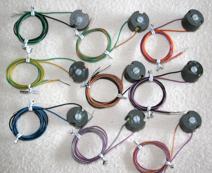
Pot Core
Inductor Set for Sphere 900
Series Equalizers
|
During the 1970's Electrodyne introduced a Mic-pre/Equalizer channel model 712 with a graphic style, inductor based equaliz er and soon it became a favorite with engineers who used them. Eventually Electrodyne sold out but the 712 design did not die. Each time the company sold, the 712 design was expanded upon. After a couple of company sales, Sphere ended up with the design and improved it by using larger ferrite pot cores and adding two bands making a total of nine bands with two being switchable creating 11 affected band choices. The Sphere 900 was born. Vintage Windings ferrite pot cores are the same size and core material as the original Sphere 900 coils. |
|
Sphere used pcb clamps to affix the coils
to the circuit board.
|
Copyright © 2013, All rights reserved. Hosting by Go Daddy. Site design by CP